3 Input 7 Segment Display Truth Table : Fpga Tutorial Seven Segment Led Display On Basys 3 Fpga Fpga4student Com
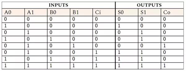
One or more such units … Each logic gate follows a truth table that gives the possible combinations of input and the respective obtained output.
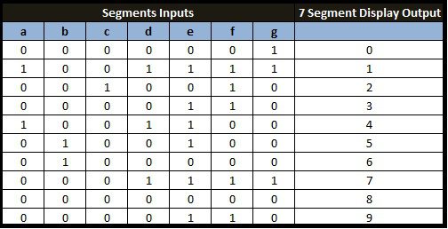
24.02.2012 · table i truth table for common cathode type bcd to seven segment decoder this table indicates the segments which are to be driven high to obtain certain decimal digit at the output of the seven segment display.
The best example of decoder. 24.02.2012 · table i truth table for common cathode type bcd to seven segment decoder this table indicates the segments which are to be driven high to obtain certain decimal digit at the output of the seven segment display. One or more such units … In the same way, other segments can also be made high. Each logic gate follows a truth table that gives the possible combinations of input and the respective obtained output. There are seven leds present in one unit of the seven segment whose combination is used to make numeral or special characters according to the use. As we know that, seven segment devices display numbers according to control signal pattern and their respective led segments turn on and turn off pattern. However, it is to be noted that in the case of common anode type, the only change will be to interchange ones and zeros on the table. Hope you have used calculators and it is our next example that depicts the combinations of logic gates. Patent 1,126,641), when carl kinsley invented a method of telegraphically transmitting letters and numbers and having them printed on tape in a segmented format.in 1908, f. The diagram below shows the led segment patterns for each digit. Although we give our input in the form of numbers, this is what happens within the device. To implement this circuit first we need to write down the truth table and simplify the logic of each segment. Decoding is essential in applications like data multiplexing, memory address decoding, and 7 segment display.
To implement this circuit first we need to write down the truth table and simplify the logic of each segment. There are seven leds present in one unit of the seven segment whose combination is used to make numeral or special characters according to the use. The diagram below shows the led segment patterns for each digit. In the same way, other segments can also be made high. Patent 1,126,641), when carl kinsley invented a method of telegraphically transmitting letters and numbers and having them printed on tape in a segmented format.in 1908, f.

The diagram below shows the led segment patterns for each digit.
The best example of decoder. As we know that, seven segment devices display numbers according to control signal pattern and their respective led segments turn on and turn off pattern. Patent 1,126,641), when carl kinsley invented a method of telegraphically transmitting letters and numbers and having them printed on tape in a segmented format.in 1908, f. 24.02.2012 · table i truth table for common cathode type bcd to seven segment decoder this table indicates the segments which are to be driven high to obtain certain decimal digit at the output of the seven segment display. Hope you have used calculators and it is our next example that depicts the combinations of logic gates. Each logic gate follows a truth table that gives the possible combinations of input and the respective obtained output. The diagram below shows the led segment patterns for each digit. In the same way, other segments can also be made high. There are seven leds present in one unit of the seven segment whose combination is used to make numeral or special characters according to the use. Decoding is essential in applications like data multiplexing, memory address decoding, and 7 segment display. To implement this circuit first we need to write down the truth table and simplify the logic of each segment. One or more such units … Although we give our input in the form of numbers, this is what happens within the device. However, it is to be noted that in the case of common anode type, the only change will be to interchange ones and zeros on the table.
One or more such units … Hope you have used calculators and it is our next example that depicts the combinations of logic gates.

Hope you have used calculators and it is our next example that depicts the combinations of logic gates.
To implement this circuit first we need to write down the truth table and simplify the logic of each segment. However, it is to be noted that in the case of common anode type, the only change will be to interchange ones and zeros on the table. 24.02.2012 · table i truth table for common cathode type bcd to seven segment decoder this table indicates the segments which are to be driven high to obtain certain decimal digit at the output of the seven segment display. Hope you have used calculators and it is our next example that depicts the combinations of logic gates. As we know that, seven segment devices display numbers according to control signal pattern and their respective led segments turn on and turn off pattern. The best example of decoder. Although we give our input in the form of numbers, this is what happens within the device. One or more such units … There are seven leds present in one unit of the seven segment whose combination is used to make numeral or special characters according to the use. In the same way, other segments can also be made high. Decoding is essential in applications like data multiplexing, memory address decoding, and 7 segment display. Each logic gate follows a truth table that gives the possible combinations of input and the respective obtained output. Patent 1,126,641), when carl kinsley invented a method of telegraphically transmitting letters and numbers and having them printed on tape in a segmented format.in 1908, f.
3 Input 7 Segment Display Truth Table : Fpga Tutorial Seven Segment Led Display On Basys 3 Fpga Fpga4student Com. The diagram below shows the led segment patterns for each digit. There are seven leds present in one unit of the seven segment whose combination is used to make numeral or special characters according to the use. The best example of decoder. In the same way, other segments can also be made high. As we know that, seven segment devices display numbers according to control signal pattern and their respective led segments turn on and turn off pattern.
However, it is to be noted that in the case of common anode type, the only change will be to interchange ones and zeros on the table 7 segment display truth table. As we know that, seven segment devices display numbers according to control signal pattern and their respective led segments turn on and turn off pattern.
Although we give our input in the form of numbers, this is what happens within the device. There are seven leds present in one unit of the seven segment whose combination is used to make numeral or special characters according to the use. 24.02.2012 · table i truth table for common cathode type bcd to seven segment decoder this table indicates the segments which are to be driven high to obtain certain decimal digit at the output of the seven segment display. The best example of decoder. One or more such units …

Each logic gate follows a truth table that gives the possible combinations of input and the respective obtained output.

Decoding is essential in applications like data multiplexing, memory address decoding, and 7 segment display. As we know that, seven segment devices display numbers according to control signal pattern and their respective led segments turn on and turn off pattern. One or more such units … To implement this circuit first we need to write down the truth table and simplify the logic of each segment.

24.02.2012 · table i truth table for common cathode type bcd to seven segment decoder this table indicates the segments which are to be driven high to obtain certain decimal digit at the output of the seven segment display. One or more such units … Patent 1,126,641), when carl kinsley invented a method of telegraphically transmitting letters and numbers and having them printed on tape in a segmented format.in 1908, f. In the same way, other segments can also be made high. Although we give our input in the form of numbers, this is what happens within the device.
As we know that, seven segment devices display numbers according to control signal pattern and their respective led segments turn on and turn off pattern.

To implement this circuit first we need to write down the truth table and simplify the logic of each segment.

One or more such units …

One or more such units …

However, it is to be noted that in the case of common anode type, the only change will be to interchange ones and zeros on the table.

There are seven leds present in one unit of the seven segment whose combination is used to make numeral or special characters according to the use.

Posting Komentar untuk "3 Input 7 Segment Display Truth Table : Fpga Tutorial Seven Segment Led Display On Basys 3 Fpga Fpga4student Com"